HDI (High Density Interconnect)

HDI (High Density Interconnect)
HDI print is a term for pattern cards where space is critical – often in mobile devices such as mobile phones, small medical devices and complex motherboards, etc., where there are many and dense lanes. HDI printing is thus multi-layer printing from 4 layers upwards with blind and/or buried vias, small holes and thin and dense tracks (down to 50 μm conductor width and insulation distance).
Most things are possible, but when it comes to solutions with buried vias in particular, it is possible to save both time and money on optimizing your design. "Standard" multi-layer prints are built up with one or more cores, which are pressed together in one pressing process. With buried vias, the card must go through several drilling, pressing and plating processes – something that takes time and costs money.
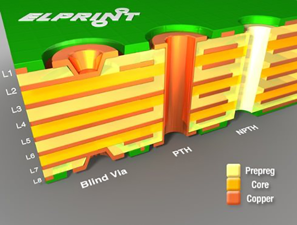
Below are examples of how 8-layer pattern cards are produced in different editions with varying complexity.8-layer built up with 3 cores (L2&3, L4&5, L6&7) with common through holes and blind vias. Blind vias must be made with a drill diameter to depth ratio of 1:1 to ensure reliable plating. They are drilled either with a mechanical drill or a laser. Blind vias are drilled after pressing a "normal" 8-layer, and there are no large additional costs associated with mechanically drilled blind vias, as no additional pressing or plating processes are required.Blind vias can be routed to a deeper layer, but then the diameter must also be correspondingly large if you want the most reasonable solution without additional processes.
It is also possible to get vias filled and possibly overplated so that they have an even surface - particularly useful with blind vias in SMD pads.Buried vias between L2-7. A "6-layer print" is produced - i.e. cores with L3&4 and L5&6 with prepreg and copper foil (such as L2 and L7) - which are pressed together. Then buried vias are drilled as through holes, and buried vias between L2-3 are made as blind vias. After the first plating process, L1 & L8 are pressed in a new pressing cycle. Then drill through holes and blind vias. Blind vias can optionally be drilled down to buried vias, so that there is contact between, for example, L2-8 - what is called stacked vias.Buried vias between L3-6. A "4-layer print" is produced - i.e. cores with L4&5, prepreg and copper foil (such as L3 and L6), which are pressed together. Then you drill buried vias L3-6 as through holes and L3-4 and L5-6 as blind vias. Then L2 and L7 are pressed, and so it continues as described above.
If desired, a connection can also only be made between L4-5 by an additional drilling and plating process in the core. It will happen before L3 and L6 are pressed (not shown in the sketch).